A heat exchange transfers heat between heat transfer fluid from a primary cooling circuit and fluid from the application to regulate process temperatures, without fluids ever mixing.
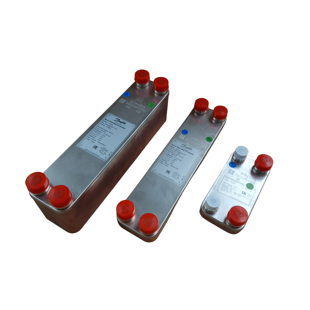
Heat exchangers in both the XF and XR series from Applied Thermal Control use plate heat exchangers in their design.
The design of a plate heat exchanger exposes fluid to a considerably larger surface area than other designs of heat exchanger, maximising the area available for thermal exchange to take place whilst keeping pressure drop to a minimum.
Front and Back Cover
These are the end plates of the heat exchanger. They are very strong, usually made from a mild steel. The purpose of the front and back cover is to hold the plate heat exchanger together.
Inlets and Outlets
Here, the plate heat exchanger is connected to the primary cooling circuit and the process cooling circuit from the application, allowing fluids to enter and exit the heat exchanger.
Heat Exchanger Plate
The size of the heat exchanger plate can vary from a few square centimetres to a few square meters. They are mostly constructed from stainless steel, titanium, or aluminium.
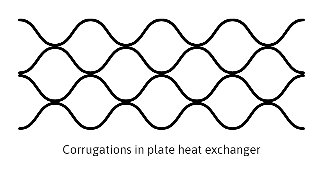
Heat exchanger plates are generally corrugated. This corrugation increases the heat exchange surface area, the rate of heat exchange, and the rigidity of the plates. The corrugations also create turbulence within the fluid, distributing heat evenly throughout. A smoother flow may allow heat to build in certain areas.
Holes in each corner of the plate behave as inlets, allowing fluid to flow through the plates.
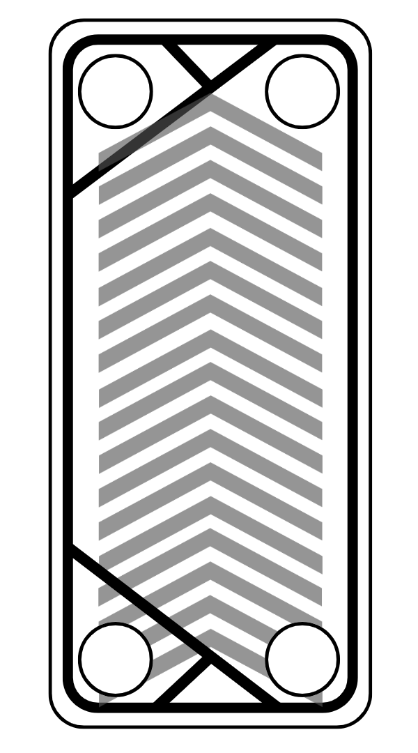
Gaskets
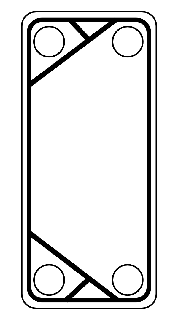
Gaskets are rubber seals attached to the front of the plate to ensure a tight seal is formed between the plates of the heat exchanger, preventing leaks or the two fluids from mixing.
The gasket is able to allow or prevent the flow of fluid into the cavities between two plates by using a diagonal seal to direct fluid as shown on the left. The gasket seals the holes on the left side of the plate, blocking fluid from entering the plate here. The holes on the right side of the plate are not sealed, allowing fluid to flow in and out of channels created between the plates.
Plates can then be stacked together, allowing fluid from the primary cooling circuit to flow through channels 2, 4 and 6, and leave the heat exchanger at a higher temperature. Fluid from the application will flow through channels 1, 3 and 5 and so on, and exit the heat exchanger at a cooler temperature.
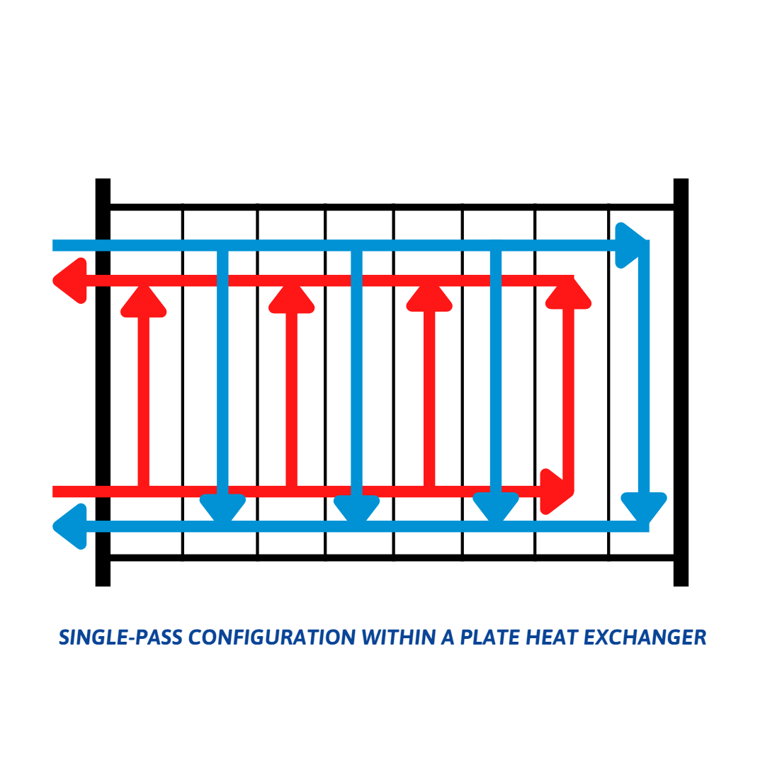
Heat exchangers from Applied Thermal Control are arranged in a single-pass configuration. Fluids are then able to then flow around the heat exchanger as shown below: